display config
Display in Vide by now knows two different states:
the "historic" java display
This display is quite slow, it is implemented using the native java graphics routines. BUT it should work on all systems
a "new" openGL graphics system
implemented via the library "JOGL" (which by now also is older than a decade :-) ). The JOGL library uses native library calls and thus might not be available on all systems. If JOGL is configured but not available - or fails to "run" for one reason or another, Vide automatically switches to the historic variant.
The "new" graphics system was only tested with a handfull of computers and is as such not guaranteed to run on all systems. If weird things happen, look at the debug output, and see if any exception was thrown - and contact me (Malban) - to improve Vedi!
That said, there are 3 different types of options:
options that work for both implementations
options that are only relevant for openGL
options that are only relevant for java native
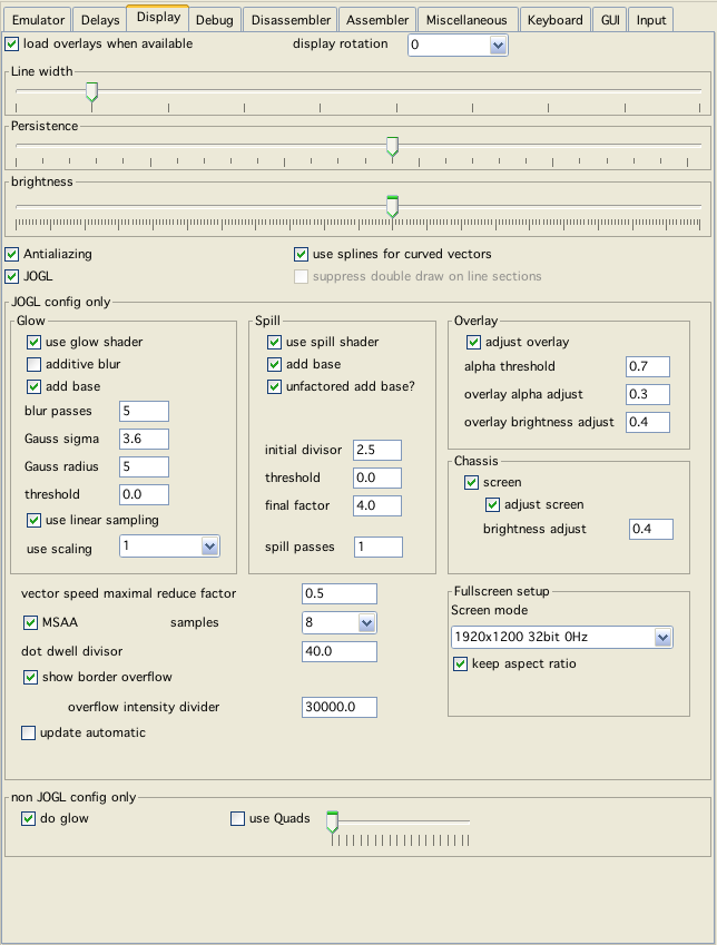
display config
Load overlay when available
Well - just what it says.
The loading of overlays follows following rules, until an overlay is actually loaded (or vide gives up) vide searches with following:
the name of a possible overlay is determined in following order:
name given in cartridge definition
name of the cartridge (without extention)
name of the rom - binary file (without extention)
to the given name a ".png" is added
with each of these names an overlay file is searched
in the current directory (wherever the current directory is)
in the main vide directory
in main directory + "overlays" (directory)
in main directory + "overlays/homemade" (directory)
in the current directory (the rom was loaded from)
if run from Vedi, also the following paths are searched:
the parent directory of the bin file
in the directory of the bin file a directory called "overlay"
in the parent directory of the bin file a directory called "overlay"
display rotation
Rotate the display to the given degrees (0, 90, 180, 270).
Line width
The thickness of one vector line. If not in JOGL mode → The thicker - the slower emulation!
Brightness
Emulating the brightness control of the vectrex!
If not in JOGL mode → The brighter - the slower emulation!
Persistence
How long does a vector "glow" after beeing displayed? If not in JOGL mode → if persistency is off (slider complete to the right), there is a slight performance gain.
Antialiazing
Smoother lines. Suprisingly at my place emulation is a lot faster with antializing switched on. Don't know why - try it!
Use splines for curved vectors
Some games/programs do curved vectors on vectrex. "Usual" emulation does not handle that all that well, it always rather looks edgy. With this option you can switch enhanced emulation with "splines" (Catmull Rom) on. If not in JOGL mode → Drawing splines is not optimized and slows down emulation. Although only very few roms use curved vectors, so you may as well leave it enabled.
Slider nearby
The slider configures how many control points are used and how they are "translated" to the drawing routine.
Other Slider nearby
This defines the maximum length (distance between to control points) that a spline is allowed to have. If the distance gets to great the spline function (which is still the correct formular) tends to "overdraw" extreme points - and that may look rather strange. The distance is given in vectrex coordinates and ranges (here) from 100 - 30000, a value in the range of 5000 has worked out rather well.
For the opengl graphics system quite a lot of options are available, most of which nobody will ever use. But while implementing the routines these were rather helpfull, so I left them in for the adventurous user.
The configuration for JOGL is done configurating so called "shaders" (if you don't know what that is - and your are interested, google "opengl" + "shader"). Different shaders are constructed by Vide on the fly using the configurations. Following different shaders can be used consecutivly to enhance the output (applied in that order):
spill shader (n times)
glow shader (m times)
persistency shader
screen shader
overlay shader
All of the above shaders can be switched on/off individually.
The spill shader is a multi pass shader, that is somewhat similar/redundant to the glow shader. It is executed befor the glow shader.
The general idea behind it was, that for Vectrex the "brightness" has no limit. Although the beam brightness maximum can be thought of being $7f, the actual screen brightness can be quite different. If a vector is drawn with a brightness of $7f with slow speed, it is much brighter than with high speed, since the same "amount" of electrons is spread over a larger area. Most visible is the effect, if you do not move at all. If you draw a dot with a brightness of $7f and keep the beam there for a considerable amount of time, you will burn a hole in the phosphor coating of the screen. It gets THAT bright.
Vide's emulation core can respect the speed and the amount of time the electron beam resides on a particular spot. The spill shader tries to get this on the screen.
What it basically was supposed to do was:
let us say the maximum brightness a "normal" monitor can display is 255
the internal brightness "count" of vide says a spot has a brightness of 873
the the spill shader distributes the excessive amount of brightness (873-255) = 618 evenly to the neighboring pixels (15% of the excessive to direct neightbors each, and 10% to the diagonals)
Theoretically this is nice and sound, but letting the graphics card do it - Vide has to use some tricks. For the graphics card, the maximum brightness is 1.0, the minimum is 0.0, so every other brightness is in between. Although all information is kept seemingly in floats, from one pass to another (or from one shader to another shader), somehow the card remembers that it is only 8 bit. So inspite of being float - you can actually only store information for a point in the range of 0.0 to 1.0.
Going back to the configuration - "initial divisor" divides all brightness data by a given factor, so that actual maximum brightness is much lower than the graphic card can calculate with. A divisor of 3 thus allows us "virtually" to not only store brightness data between 0-255 (or 0.0 - 1.0) but between 0 - 765 (0.0 - 3.0) since all input is divided by the given factor (3).
The spill shader now looks whether a brightness is higher than that divided brightness max (for the example 85 (or 0.33), and if so - spills the accessive amount of brightness to its neighbours.
Since the data might not all be spillable in one pass (spilling to already "full brightness points" e.g.) you can give the number of consecutive "spill passes" that you want.
"final factor" is the reverse factor - with which the shader concludes its working and sets the data again to the "natural" brightness of the card 0-255 (or 0.0 - 1.0).
"threshold" defines the threshold, when that "spilling" should occur. In the above example the threshold was implicit "1.0" (or whatever you want to see as the maximum) - but with the variable threshold, you can also define, that spilling might start at "half" the brightness (0.5) or any other value you might want.
"add base" adds the complete input data to the output data. "unfactored add base" only takes effect, when "add base" is selected - if selected than the original data is added. If not selected, the original data is added after the initial divisor was applied.
Spill-Note
The thoughts behind the implementation of the spill shader might have been ok-ish. As you can see - the currrent use of the spill shader is quite different than what I explained that it does. It actually adds to the overall display in my oppinion, but the result that is used was gotten by trial and error and experiments, rather than the result from carefull planning.
This is a classic gaussian blur shader. It uses "classic" vertical and horizontal passes and can make use of linear sampling (which surpisingly gives slightly different results - I probably did something wrong within the shader - but have not been able to track it down).
The meaning of the fields can be gotton from Wikipedia.
As an addition:
you can also configure scaling (the blur is scaled down with the given factor and after bluring upscaled again)
you can configure whether each pass "adds" to the last or not
and as with the "spill" shader, you can add the original input again to the output.
Is also realized with a shader. Basically the last image vecxy produced is added with an applied alpha value to current image. The slider persistency here is than actually the alpha value and the only thing you can configure.
The screen idea was taken from ParaJVE - and thus from Franck Chevassu. The image I use actually is some kind of special overlay. It is drawn after the above shaders. The only possible configuration is an additional brightness setting, which makes it appear more or less clearly.
Vide uses the "normal" PNG overlays which are "available" (Mess e.g.). Like Franck before I realized, that printing them to screen 1:1 looks not always the best. For Vide a special shader for the overlay display was built, that can enhance the use of the images. Overlays usually consist of pixel information of different kinds, the one "needed" here is in general the alpha value of a pixel (how opaque or transparent it is). The internal changes the shader applies - it applies only to pixels it thinks of as transparent. The first value is used to configure that "alpha threshold" - technically speaking, each pixel with an alpha value below the given value is treated as "transparent", every pixel above the value is treated as opaque. In the above sense opaque pixels are drawn to screen as they come (if they still have some alpha value - that is respected). In the above sense transparent pixels may have one or two transformations applied
overlay alpha adjust
In general means the transparent pixels are made even more transparent. The original alpha level is multiplied by the value given here (If you really want, you can also make them more opaque).
overlay brightness adjust
If the transparent area has a "vector" underneath it, the alpha value is additionally adjusted (added to) with the brightness of the vector multiplied with the "overlay brightness adjust" value.
What this actually boils down to is:
the higher the value the brighter the vector in the actual overlay color is drawn
the lower the value the less color of the overlay is used by the vector (zero means the vectors do not use overlay colors at all and are drawn in white)
Note
The overlay images Vide uses at the time of writing use quite different "alpha" values. For that reason it is possible to define the alpha threshold also within the cartridge - if defined there, has preference over the value defined here. The default value is 0.8. But e.g. the minestrom overlay looks much better using a value of 0.5.
vector speed maximal reduce factor
Mentioned before - the faster a vector is drawn with a fixed brightness - the less bright a vector actually is. With this factor you can configure Vide how pronounced this effect should be displayed.
MSAA
MultiSampleAntialiazing - this setting only takes effect if the general "Antialiazing" option is switch on. Opengl knows two different options to implement antialiazing. The old option "SMOOTH" may not be implemented in hardware, but by software - the actual graphics card driver. "SMOOTH" may be considerably slower than "MSAA" - which is implemented by the graphics card in hardware.
The samples tell the graphics card with how many samples it should do the antialiazing.
Note
The values for the samples are fixed - these are not gotton from the card. Thus if you configure a value that your graphics card is not capable of - vecxi will only show a blank screen (but there is no danger involved :-) )
dot dwell divisor
Drawing dots is in many ways special - not the least is how "bright" a dot may be. With this setting you can influence the brightness of dots.
show border overflow
If - on a real vectrex you draw way outside the normal screen range - parts of the border "glow" with some kind of an aftermath of the not printable vectors. If this option is switched on - vide tries to emulate this. This option might slow down emulation ever so slightly).
The accompanying "overflow intensity divider" influences the strength of the effect.
Note
Different real life hardware vectri have different "out of scope" ranges. E.g. there are vectri which display Frogs "EmptyScreentro"-demo as out of scope. While I have a Vectrex where the drawing actually is "in scope". The scope of emulation can be set with "emulated vectrex integrator max" - see tab emulator.
Fullscreen setup
Only two settings:
which screen mode to use (values gotton from your hardware, as Java sees them)
whether to keep aspect ratio
Note
Despite it saying "fullscreen setup" - the aspect ratio setting is "general" - which is also usefull with screen rotation.
do glow
An option that tries to visually emulate the "glow" of vectors. Results are also dependend on "Line width". Glow really slows emulation, especially higher glow values. But it is so pretty!
Above "brightness" directly relates to glow. If glow is disabled, the brightness slider has no effect!
Some emulated "effects" are only visible if glow is switched on.
e.g. "dots" are usually drawn using a dot dwell time (time the vector beam resides on one single spot). The higher the dwell time, the brigher the dot.
vectors are drawn with different "strength" values, the strength actually is the speed with which the vector is moving. The higher the speed, the less time the electrons are positioned at "one" location. Thus the higher the speed, the lower the brightness of one vector
Both effects (the second only very barely) can only be seen if glow is enable!
Use Quads
Belongs to spline configuration, this is only active if splines are switched on. Drawing "Quads" is more performant than splines, but some curves look bad... I do not recommend this setting and it is available more for historic reasons than for any real value!