pwm
(extracted from: http://www.allaboutcircuits.com/textbook/semiconductors/chpt-11/pulse-width-modulation/ - written by Tony R. Kuphaldt, Design Science License)
Pulse Width Modulation (PWM) uses digital signals to control power applications, as well as being fairly easy to convert back to analog with a minimum of hardware.
Analog systems, such as linear power supplies, tend to generate a lot of heat since they are basically variable resistors carrying a lot of current. Digital systems don't generally generate as much heat. Almost all the heat generated by a switching device is during the transition (which is done quickly), while the device is neither on nor off, but in between. This is because power follows the following formula:
P = E I, or Watts = Voltage X Current
If either voltage or current is near zero then power will be near zero. PWM takes full advantage of this fact.
PWM can have many of the characteristics of an analog control system, in that the digital signal can be free wheeling. PWM does not have to capture data, although there are exceptions to this with higher end controllers.
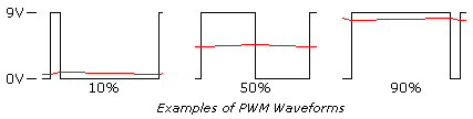
One of the parameters of any square wave is duty cycle. Most square waves are 50%, this is the norm when discussing them, but they don't have to be symmetrical. The ON time can be varied completely between signal being off to being fully on, 0% to 100%, and all ranges between.
Shown below are examples of a 10%, 50%, and 90% duty cycle. While the frequency is the same for each, this is not a requirement.
pwm
The reason PWM is popular is simple. Many loads, such as resistors, integrate the power into a number matching the percentage. Conversion into its analog equivalent value is straightforward. LEDs are very nonlinear in their response to current, give an LED half its rated current you you still get more than half the light the LED can produce. With PWM the light level produced by the LED is very linear. Motors, which will be covered later, are also very responsive to PWM.