basic scheme
basic scheme
(picture stolen from: http://enlight.ru/post/9479/)
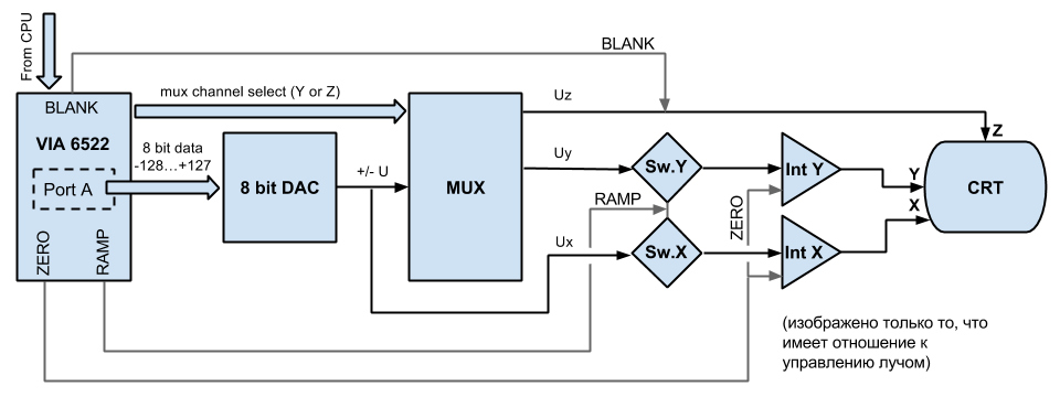
For a very general idea of the vectrex hardware, look at the diagram.
I will try to describe the diagram with my own words, perhaps it will help :-).
What do you want Vectrex to do?
YES, draw Vectors, that is what this is all about. To draw something you need something to draw upon, back in the 80ies screens to draw upon were large, heavy and were powered with huge voltages. The underlying principal was called Cathode Ray Tube, or short CRT, thats what is on the utter left of the diagram. Your vectrex "monitor".
To draw a vector you basically shoot some electrons at a phosphor coated piece of glass, the phosphor begins to glow and you recognise that as a bright spot on the outside. To draw just one point is sort of boring, thats why people wanted to "move" the spot. Luckily electrons happen to interact to magnetism. And luckily technology enables us to "control" magnetism. We don't need a man standing beside the screen and juggling with little magnets to deflect the electron beam :-)!
If you have a copper wire, and some current running thru it, you also have a magnetic field around the wire. With some mathematical background you can calculate the magnetism and build nice things, like transformers, wireless iphone rechargers, induction cookers etc - all the same principal. But lucky for us also deflection coils for CRTs... ehm, I am drifting away...
Where was I? With the help of deflection coils you can change the path the electrons take and so move the bright spot on the screen any way you like.
If you move the spot from left to right switched "on" than from right to left switched off, this 625 times with a tiny bit down every line, you are pretty near the PAL television norm, at least if you do that 25 times in one second.
Vectrex can't draw 625 "fullscreen" lines 25 times a second. It's no TV.
Anyway, going back to vectrex, and what it CAN actualy do.
Vectrex has more or less DIRECT controll over the beam. In the diagram you can see three lines connected to the CRT: X, Y and Z.
X - is the X position of the spot Y - is the Y position of the spot Z - is the brightness of the spot
These input lines to the CRT are ANALOG voltages.
How do we get from our digital world to analog values for the positioning of the spot on the CRT?
Ok
Lets go to the other side of the diagram.
The Microprocessor of the vectrex does not communicate directly with any analog part. It uses the VIA 6552 to comunicate with all periphals.
The CPU only knows 16 registers of VIA and pokes and peeks to/from them to achieve control over the beam.
The relevant VIA parts and its analog pendants are:
CA2 - ZERO
CB2 - BLANK
bit 7 of ORB - RAMP
bit 0 of ORB - mux enable
bit 1-2 of ORB - mux select
ORA - input to DAC
This is a wild mixture of "things" Via has to offer!
CA and CB are "Control Lines" there are 2 control lines each for "A" and "B". The control lines can generate interrupts, can be used as input or output and "B" can be "driven" by timers. The behaviour of these control lines is internally controlled by register $c [Control Register].
The bits of the ORB can theoretically be both input and output, the above bits are ONLY used as output! Bit 7 is "special" in the way, that output can also be "controlled" by the timer 1 of VIA.
ORA is used as "direct" input to the DAC.
No matter how these signals are generated internally by VIA the following for the analog section of vectrex is the result:
CA2 - ZERO
If CA2 is 0 than the "ZERO" signal is active! If CA2 is 1 than the "ZERO" signal is NOT active!
CB2 - BLANK
If CB2 is 0 than the "BLANK" signal is active! If CB2 is 1 than the "BLANK" signal is NOT active!
bit 7 of ORB - RAMP
If bit7 is 0 than the "RAMP" signal is active! If bit7 is 1 than the "RAMP" signal is NOT active!
bit 0 of ORB - mux enable
If bit0 is 0 than the mux is enabled! If bit0 is 1 than the mux is NOT enabled!
bit 1-2 of ORB - mux select
If mux is enabled, this two bit number selects the DAC output.
ORA - DAC Value
The DAC input is THAT value.
In short zero means "ground", if you look at the diagram the zero line is connected to both integrators. If ZERO is active, than the integrators are grounded, and no matter what values are present there is no integration ongoing. If an integration happend befor, values are resetted! If zero is active and you as a programmer try to draw something - all you will see is a bright spot in the middle of the screen - the point zero!
ZERO ing the integrators takes time. Measures at my vectrex show e.g.: If you move the beam with a to x = -127 and y = -127 at diffferent scale values, the time to reach zero:
scale $ff → zero 110 cycles
scale $7f → zero 75 cycles
scale $40 → zero 57 cycles
scale $20 → zero 53 cycles
After these I stopped my (tedious) measurements.
Just remember, not to draw vectors to early after doing a ZERO.
The same thing as ZERO only this time for the brightness of the beam, not the position. If BLANK is active, the beam is switched off, no matter what other brightness you might have set befor.
The RAMP signal enables or disables integration. In the diagramm the RAMP line is connected to "switches" befor the integrators. If RAMP is active, the switch is in ON position and integration happens. If not, NO integration is possible. But the integrators "hold" their values (well for a little time anyway). It is not possible to switch only one of the integrators on or off, you do always set RAMP for both! If you don't want to integrate the other one, set the "integration value" to 0.
As seen in the diagram, the output of the DAC goes as input into the MUX. If mux is enabled, than the DAC (analog) value is sent to its destination (given by mux select). If mux is disabled, NO output is done to any of the mux lines. (BUT: as you can see the output of the DAC goes directly to the X-Integrator input (switch). Regardless of the MUX, x-integrator ALWAYS recieves the current DAC output!)
These two bits are used together to build a 2 bit value. This two bit value ranges from 0 to 3. According to the resulting number, the multiplexer switches the output of the DAC to the respective recieving hardware:
0 (binary: 00) Integrator for vector y-position
1 (binary: 01) X, Y integrator offset values
2 (binary: 10) Z-value of vector hardware (brightness)
3 (binary: 11) audio hardware
Not discernable on the diagram is, that for the line 0 and line 2 (y-Integration and Brightness) the values that are set are hold till set to another value. Responsible for holding are the op-amps of type IC LF347(s). For setting a value one can also say, that the current DAC value is a (short) "sample", and these sample values are on hold till new samples arrive. In many documentations you may find "sample and hold" values. The values that are set to the above four different destinations are those "sample and hold" values.
The DAC translates a 8bit input (-128 - +127) to an analog voltage ranging from -5 volt to +5 volt to its output
If you want to draw a vector there are some items you allways have:
start position e.g. 10, -10
end position e.g. 20, -20
brightness e.g. 50
If you want the analog hardware to draw a vector you must give it these values in a form that it can understand.
There are some things to assume befor we start drawing.
BLANK is ENABLED
ZERO is ENABLED
RAMP is DISABLED
MUX is DISABLED
This is the "standard" beginning of a draw procedure. In terms of analog hardware the following must be done:
set brightness
DAC = 50 (brightness value to DAC)
mux sel = 10 (select brightness output in mux)
mux enable
mux disable
[note: blank is still enabled!]
[This short "mux enable/disable" is "enough" so that the brightness is set to 50. The "storage" position (sample/hold) for brightness is nowhere to be found in the diagram]
move to 10, -10
DAC = -10 (y coordinate)
mux sel = 00 (y integrator)
mux enable
mux disable
now y integration value is set to -10 [one could say (regarding the diagram) that the y-integration value is stored by the "y-switch" (- again sample/hold)]
DAC = 10 (this sets X-intgeration value to 10)
ZERO = 1 (ZERO not active!)
RAMP = 0 (enable RAMP, integrators are working)
wait for a defined time (in real life this is the scale factor)
RAMP = 1 (disable RAMP, integrators are not working)
[now we are at position 10, -10]
draw vector to 20, -20
The drawing of a vector is usually relative, so here we are not using 20, -20 but the difference (offset) to our "current" position, which is exactly 10, -10 again, so we can reuse the values for the integrators we already set above!
BLANK = 1 (disable BLANK, the phosphor is shining!)
RAMP = 0 (enable RAMP, integrators are working)
wait for a defined time (in real life this is the scale factor)
RAMP = 1 (disable RAMP, integrators are not working)
BLANK = 0 (enable BLANK, beam is switched off)
[now we are at position 20, -20, and have just drawn a vector]
The actual assembler code looks a little bit more complicated, since the analog "objects" can not be set directly. The BLANK is usually set "through" the SHIFT register of VIA, which in turn is set up by the auxiliary control register. The RAMP is (often) controlled by the timer, which in term is controlled by the control register ...