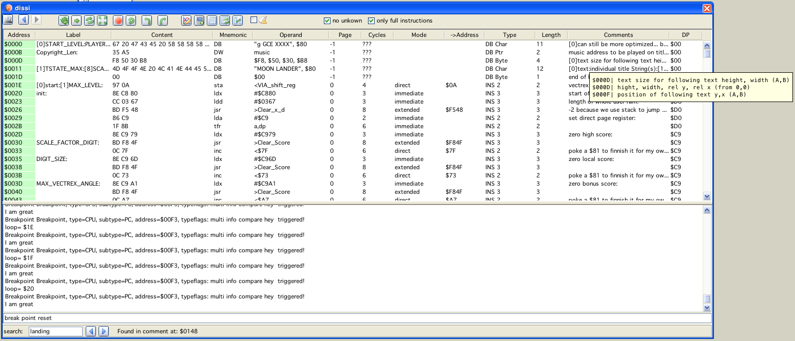
dissi window
dissi window
Dissi only shows sensible data that was LOADED from a file, dissi does NOT read data from the emulator, all addresses not loaded are marked as "unkown" and contain for the purpose of dissi only a "0" (null). That means it is not possible to look at RAM or IO locations and per default these are hidden from view!
If no help is given (in form of information, see below) dissi tries to disassemble the given file as follows:
it assumes the file is a valid vectrex file, meaning it searches the start of the file for a vectrex header:
copyright string
music
text display list (with size and position information)
0 (zero)
assumes code therafter
"assuming code therafter" in general is kind of difficult, because if data is encountered dissy tries to interprete data as code and that looks most of the time pretty silly - so please help dissi!
dissi always tries to disassemble the file so that assi can compile the generated source code to be 100% the same binary as was given in the first place
for that at all to be possible (see bulletpoint 2) dissi even without help must generate data, because there are data bytes that have no representation as an assembler mnemonic, or a postbyte is illegal for a correct mnemonic
dissi generates DB data values for those occasions and provides a line comment for its reasoning
in general dissi would be grateful, if you discover "bunches" of such generated DB-Data, that you provide help and mark these ranges as DATA (which is just a drag, a click and another click to save them for next time)
Using vide there will only be one "instance" of dissi and its children be available - usually that will be "enough". In the seldom cases when it might be usefull [debugging link cable connected vectri] to debug two vecxi instances at the same time (in opposite to the non usefull cases, where the user just wants to play around) you can switch dissi from one vecxi to another vecxi by pressing the  button on the vecxi instance. Pressing that button ensures that dissi is connected to THAT vecxi instance. Pressing the button also clears all breakpoints (only if dissi realy was connected to a different vecxi instance), after all - where should the debugging be done for a breakpoint - if there is no dissi anymore...
Buttons
For dissi and its "children" you can often find the following icon in the uper left corner:
 always update
(that is a "switch" button!) which means the contents of this window will be updated "always". This mainly refers to when not in debug mode. The term "always" is a bit misleading. Always here means after each "emulator call". This does not mean "after each emulated instruction". The later is only true, when in single step or continuous mode. When the emulator is in "play" mode, each emulator call approximately emulates 30000 cycles worth of instructions.
Following buttons are available for dissi:
debug
start debuging (program halts for now), also opens a "regi" window
 single step
perform one single step, all output/status windows are updated
![]() overstep
overstep
the next "one time" breakpoint is set after the address of the next instruction. This means, the next instruction is emulated, and e.g. if that one is a JSR to some other place, that whole subroutine is executed and the program will be halted after returning.
![]() step out
step out
if the program is performing a subroutine, the next "one time" breakpoint is set to the top most callstack address
 breakpoint
a breakpoint is set at the current selected address in "dissi".
Breakpoints are ALWAYS active, even when not in debug mode!
![]() continuous single step
continuous single step
single step until breakpoint is hit, or the user interferes
![]() undo
undo
undo the last emulated instruction. The size of the undo-buffer can be configured (up to 50000 steps).
holding SHIFT does 10 steps holding CTRL does 100 steps holding SHIFT and CTRL does 1000 steps holding ALT does 10000 steps ![]() redo
redo
the next "state" in the ringbuffer of undoable state is set. If I did everything correct, this should be exactly the same as performing a single step. Although, performing a "real" single step "resets" the redo "pointer".
Note: For both above undo/redo:
![]() undo 30000
undo 30000
step back 30000 steps (not cycles!). Independend of the above mentioned single step back one can configure a secondary step back buffer (up to 5000). Each step takes back the last 30000 assembler instructions. Each of these "big" steps erases the single step buffer.
![]() redo 30000
redo 30000
The opposite of the just described "large" step back.
 tracki
opens a tracki window
 viai
viai
open a monitor window for the 6522
 dumpi
dumpi
opens a memory dump window
 vari
vari
opens a variable listing window
 labi
labi
opens a label listing window
 ayi
ayi
opens an ayi window
 breaki
opens a breaki window
 profi
profi
opens a profi (profiling) window
 vinfi
vinfi
this will enable a mouse pointer in the emulation window. You can select any displayed vector and get information about it. Upon selecting a vector a "vinfi" window opens.
 write file
This writes a source file of the current dissi contents to your hard drive. The file generated will save to the location the current bin file was loaded from and has a file extenstion of *.dasm.asm".
Shift click will save a "clean" assembler file. Clean, as in no variables, defines, equ or whatever. Just plain assembler with lots of numbers!
If the current cartridge has more than one bank, a file is generated for EACH bank.
 write cnt file
This writes the current collected or individually gained information of dissi to a cnt file (or more than one if banks are used). This is the only way to persist your comments and insights. Use it!
 save vector screenshot
Saves the current vectrex display as a vectorlist to use in vecci.
 history back
Within dissi you can easily "jump" from one address to the next, dissi keeps a history of these "jumps", with these buttons you can navigate your history
 history forward
...
The main part of "dissi" is occupied by a "memory" table. Each line represents one memory location of your vectrex. Per default unkown locations are hidden. Addresses which are "part of other" addresses are also per default hidden (both can be viewed toggling the two checkboxes in the upper right area).
It is worth mentioning, that if a dumpi window is displayed, and on dumpi the switches "data display" and "active" are activated, that each selection in dissi is also taken as selection in dumpi. This way you can select regions (vectorlists or bitmap data) also in dissi and use dumpi as a "preview" window for the selected data!
The columns of the table are more or less self explainatory, here some more information:
Column 1 - Address
This is the memory location where this line starts. Machine code instructions can occupy more than one memory location, as do "groups" of bytes, words or chars. Per default one group of such data is displayed per line. The next address will be the one after the grouped memory locations.
SHIFT-mouse click opens dumpi at address.
Column 2 - Label
This column contains all known labels for that address (group). If there is more than one label, they are seperated by a ":". Single click on a label cell, will hightlight the first label in the operand entry of the table.
Labels can be edited! When you enter the editor, you see all labels for exactly the address of that line seperated by a ":" (in opposition to when you are not editing, than you can see all labels belonging to the corresponding instruction group of that address).
You can enter new labels, delete old ones as you like.
The disassembly after finishing editing the labels will change accordingly.
If you "delete" any of the old labels, the reference in the source will be replaced with the first label in the list.
Changing the order does not change references.
Adding a new first label does not change references.
deleting the last label will either replace the reference with the actuall address (or offset), or generate a new label on the fly (depending on dissi configuration settings)
there is no "syntax checking" on edited labels, if they contain spaces or otherwise "bad" characters, than "bad luck" if you want to assemble exported sources
Column 3 - Content
This is a hex-byte representation of this memory location (group)
Column 4 - Mnemonic
A Mnemonic representation of the underlying manchine language instruction - or a pseudo opcode for data (DB, DW). Double click on an instruction will open a small help for the mnemonic (stay on top window).
Column 5 - Operand
Underlying operand of the machine language instruction or a representation of data.
If the operand represents a BIOS (Bruce Tomlin style) routine, you can double click the operand, and a small help (stay on top window) will be displayed. If the operand denotes a RAM location (variable name), than vari pops up with the denoted variable selected.
Column 6 - Page
one of four possible states:
0 - page 0 opcode
1 - page 1 opcode
2 - page 2 opcode
-1 - data
Column 7 - Cycles
The number of cycles an instruction takes (or ??? for data)
Column 8 - Mode
If the instruction has an "address mode", than it is listed here (empty otherwise). Possible states are:
- immediate
- direct
- extended
- indexed
- relative
- inherent
Column 9 - →Address
If column 9 was one of (direct, extended, relative) the resulting "target"-address is listed here. If the resulting address is a 16bit address, the tooltip will show the contents of that location. A double click on the address will move dissi to that location (8 bit addresses are interpreted as relative jumps, 16 bit addresses as absolut jumps). In many cases this convention makes sense - not in all. A SHIFT double click opens dumpi at that address location.
Column 10 - Type
The type of the memory location. Can be one of:
- DB Char
- DB Byte
- DB Ptr
- DB Word
- INS 1
- INS 2
- INS 3
- INS 4
- INS 5
- INSPart 2
- INSPart 3
- INSPart 4
- INSPart 5
Column 11 - Length
Length of the instruction in bytes - or the length of the grouped data in bytes.
Column 12 - Comments
All comments belonging to the address. Seperate lines are seperated by ":". All comments are displayed by the tooltip! Comments can be edited - as labels only for exactly the address of the current row.
Column 13 - DP
Guessed or set direct page register dissi thinks appropriate for that address. This is not always correct!
additionally some columns can be displayed while profiling
popup window
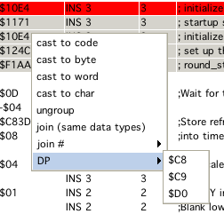
Selecting rows in dissi enables you to change the "display" of the data on the fly. Right clicking opens a popup. Selecting the menuitems applies the selected entry to the currently selected rows (and their represented addresses). Following options are provided:
cast to code
casts the selected rows to be "enforced" to code
cast to byte
casts the selected rows to be "enforced" to byte data
cast to word
casts the selected rows to be "enforced" to word data
cast to wordpointer
casts the selected rows to be "enforced" to word pointer data
cast to char
casts the selected rows to be "enforced" to char data
ungroup
ungroup selected rows (if possible, code e.g. can't be ungrouped or joined)
join
groups selected rows, ALL selected (if possible, data which are not ascii e.g. can't be char-joined)
join #
group to selected number (2-6)
DP
set direct page register (what dissi is led to believe the dp is) to one of $c8, $c9, $d0
use label as data You can force a label to be also be recognized as "immediate data". If you force that, dissi is able to use an address in immediate addressing. That means, if e.g.
$c880 has a label start_ram
and an assembler directive like:
LDU #$c880
is encountered, dissi than can recognize the immediate label and output:
LDU #start_ram
... for better readability.
There are not many yet - dissi is still in development:
"SPACE", sets or unsets a breakpoint at the current row.
"R", run (disables debugging, till a breakpoint is hit)
(This is not finished yet) Below the main table is a split panel, which again consists of two entities.
a "message" board, which at some stage might give you some feedback of what you are doing
a commandline where you can enter dissi commands without getting dizzy from all the mouse movements (although, this is a part which is not complete yet).
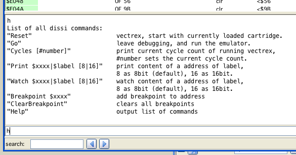
dissi commands
h shows a help of the current available commands, ...
these will be expanded as I need them, as of now following "written" commands are available:
hardreset
softreset
go
cycles (set or read)
run cycles
count cycles (between two addresses)
print (memory location)
breakpoint address, upon bankswitch, or any bit of VIA/ ORB, or ROM, PC, NZ
label reset (all automatically build lables)
clear ALL breakpoints
information about current cartridge
switch debugger to bank #
remove all automatically build "error" comments
toggle display about when a bankswitch occurred
cls
poke $xxxx $yy [change any memory location]
sync bank comments
carti
joyi
bankswitch debug
set xx yy
watches
rd
quiet
(as you see, these were commands that I at some stage needed while hacking VIDE together :-))
You can enter simple "expression" and use the cli as a small calculator. Conversion between decimal, binary and hex is also supported.
Note:
Using the CLI you are able to set breakpoint otherwise not accessable.
ROM
triggers a breakpoint when the cartridge tries to write to ROM area
PC
triggers a breakpoint when the PC is pointing to a location not usually used for execution (area outside current ROM + BIOS)
NZ
triggers a breakpoint at the defined location if the integrators are not in a close range to the zero point
VIA ORG
can trigger a breakpoint upon the specific state of one bit of VIA ORB
On the bottom of dissi is a search field. Searches covers all kinds of labels and commentary
Entering any text will hightlight the operand cells, that contain a match.
In order to satisfy old debugging habbits (of doing a "System.out.println(...)" or a Console.writeln("...") or whatever) - I implemented a "hey dissi" routine.
In short, you can tell your source code to output information to the dissi message board. Everything works in form of comments. How comments are entered - see below (CNT, LST or ASSI, which of these is of no importance, as long as dissy knows the comments, when a vectrex program is executed).
As of now there are only a couple of commands implemented, but if needs arise I can improvise and supply more :-).
The comment syntax is quite easy, dissi parses all comments and if it finds the keywords:
hey dissi
It knows that you are talking to it. Dissi than takes the string it finds after "hey dissi" which is expected to be in quotes and tries to interprete it as commands.
Dissi as of now only knows the following commands:
print
print some information
break
insert a breakpoint here (option parameters: "once", "integratorzero" - see NZ)
watch
add a watch
Example 1:
; hey dissi "print I am great"
Will output
"I am great"
Whenever this line is passed in emulation. The emulation is not stopped, only the string is printed.
Example 2:
; hey dissi "print value of $c9b5"
Will output
"value of $c9b5 = $89"
(in case the memory location of $c95b equals $89 at the time)
Example 3:
; hey dissi "print value of $loop"
Will output
"value of loop = $01"
(in case the memory location of the label "loop" equals $01 at the time)
In short:
you can output any text after a print provided in quotes
you can give the print command a 16bit hex-number which must start with a "$", it than will print that address and the 8bit value stored in that address
you can print any known "variable" and its 8bit contents, the label must be proceded by a "$"
technically the string in the parantheses is "split(" ")" and all resulting words are interpreted with the above syntax, so in one line you can print as much as you like
Note:
The parameters must be seperated by whitespaces from each other. E.g. a "print Joystick=$Vec Joy 1 X" does at the moment not work, there must be spaces befor/after the variable.
Note:
As of yet you can not ouput 16 bit values, if you want to do so you must output 2 eight bit values and use your brain.
Registers
You can also print registers, to do so, write a "#" befor the register.
Example:
; hey dissi "print #a #b #x"
Example 4:
; hey dissi "break"
Will simply add a breakpoint to that line. Program execution will be halted.
One can also add an additional parameter "once" - to configure dissi to only use the breakpoint once.
Example 5:
; hey dissi "watch RecalCounter"
Adds a watch to a variable called "RecalCounter", per default the locations watched are watched as "bytes".
An additional type parameter can be given after the variable (or memory address):
0 - displays watch as binary
1 - diaplays watch as byte value
2 - displays watch as word value (16 bit)
3 - displays watch as string (till a byte <= 0 is found)
4 - display two consecutive memory locations as seperate byte values
5 - displays a sequence as byte values, sequence length is determined by another additional parameter
The watch parameter can be places ANYWHERE in the source code.
There are three (plus one) ways to supply dissy with information.
if you happen to use as09 from: Copyright 1990-..., Frank A. Vorstenbosch, Kingswood Software.
You can use the "LST" files that this assembler generates. If the "LST" file is in the same directory as the rom file, it will be loaded automatically.
Compile your source file with assi in VIDE.
edit dissi (and save the edited entries)
Supply a "CNT" file, if the "CNT" file is in the same directory as the rom, it will be loaded automatically.
You can create CNT files manually, but you will usually do is either:
assemble a source code with assi - than an cnt file is generated automatically
comment a "bin" cartridge in dissi - and save your comments - saving "knowledge" in dissi alays saves to a cnt file
Saving is always done to the same directory the binary file was loaded from. In opposition to that cnt files are loaded in the following manner:
first dissi tries to load a cnt file in the directory the binary file as loaded from
after that a directory "cnt" is looked for and if found, a cnt file for the binary file is looked for there
A CNT file is a description file for a rom. There are a handfull of entries you can provide. If done with enough endurance and research you can supply a whealth of information. Following entries are possible:
START BANK x / END BANK x
All entries between those tags are only relevant for the given bank. The same CNT file can be used for different banks, but all information not belonging to the corresponding bank are ignored.
If no start or end is given, all information are considered to be relevant for bank 0.
After an END BANK x the default switches back to bank 0.
(Not parsable numbers/characters are treated also as bank 0)
END BANK x
EQU
Defines a "constant".
Example:
EQU VECTOR_LENGTH 0x10
EQU LENGTH_TIME $A0
EQU LENGTH_POS_X 20
LABEL
Defines a "label".
Example:
LABEL $F192 Wait_Recal
DIRECT_LABEL
Defines a "label" for DP addressing, with this option you can assign different names to same values and have dissi enabled to discern the two.
Example:
DIRECT_LABEL $D0 $00 ORB
DIRECT_LABEL $D0 $01 ORA
DIRECT_LABEL $C9 $00 Ship_counter
FORCE_SYMBOL
At the given line dissi should use the following symbol in disassembly. (only makes sense if there are different labels with the same definition to chose from) (if there is no fitting symbol (value related) this is ignored). Example:
FORCE_SYMBOL $2622 ship counter
FORCE_NO_SYMBOL
At the given line dissi should not use any symbol (but a number instead). Example:
FORCE_NO_SYMBOL $2625
COMMENT_LINE
Adds a complete line of commentary befor the given address.
Example:
COMMENT_LINE $0020 From here on, the wonderfull vectrex program will do ...
COMMENT
Adds a comment to the end of the instruction (group) beginning at the address.
Example:
COMMENT $0022 Plus 1 here because the ship exploded yesterday ...
COMMENT_LABEL
Adds a comment to a label (this is mainly interesting for labels in RAM).
Example:
COMMENT_LABEL $C89F Amount of shrimps the player has eaten ...
RANGES
The range keyword has several subdivisions, which all work alike.
First the examples, than a quick explaination.
Example:
RANGE $17 - $28 CHAR_DATA
RANGE $1917 - $1943 DB_DATA
RANGE $1913 - $1917 BIN_DATA
RANGE $1913 - $1917 DW_DATA
RANGE $2913 - $2917 DWP_DATA
RANGE $1943 - $3499 CODE
RANGE $1B2D - $5255 DP $D0
Essentially tell dissi what kind of data/code it has to expect. The example shows all six different type of ranges currently implemented.
CHAR_DATA
Are Vectrex "ASCII" chars, usually terminated by a $80.
DB_DATA
Byte data.
BIN_DATA
Byte data as binary.
DW_DATA
Word data.
DWP_DATA
Word pointer data.
CODE
Code, here dissi should be put to work!
DP
Tell dissi to expect DP to be set to the following value.
The first four of those ranges can have an additional value added. A number describing the maximal group length. If supplied, dissi tries to group the data found in the range into groups with that length.
Example:
RANGE $1917 - $1943 DB_DATA 5
Will group data into "packages" of five:
DB $10, $ff, $03, $06, $0c
DB $10, $ff, $18, $0c, $08
DB $10, $ff, $01, $02, $02
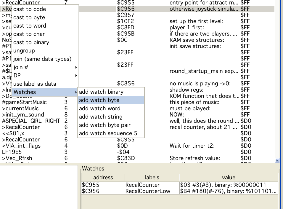
Watches
Watches are "quick" views right inside the dissi window of certain memory locations. Watches can be defined via command line (see help there), as "hey dissi" commands (see there) or via a popup menu. The value of the "operand" is determined (if possible) and used as the watch memory location.
Clicking on the watch itself displays another popup with which the watch can be removed.
In order to test the assembler, I wrote a special version of dissi, → cdissi (compare dissi).
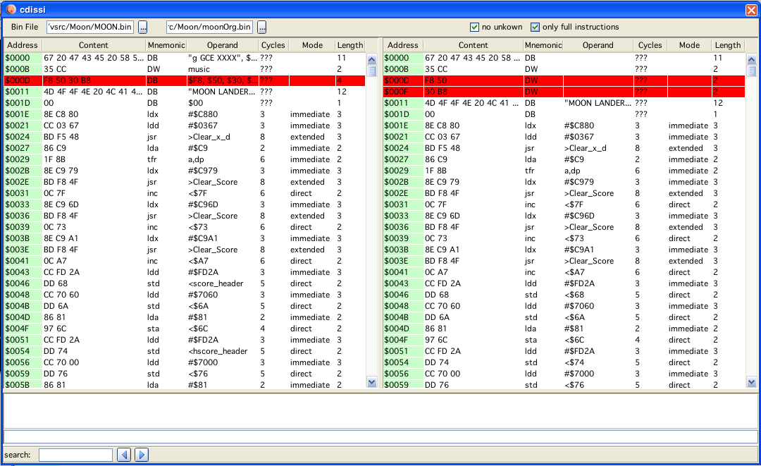
compare dissi
CDissi only makes sense if you have two nearly identical binary images.
You can load both of them and have them displayed side by side.
Both lists are in sync, and can not be unsynced.
"Rows" in dissi are compared address wise. All that are equal have white background, all that are different are red.
Below the table you can enter a start and an end address for a CRC generation for both loaded files.
Note:
Format (byte, word, char, code) of the output is respected, so the same data as word and byte shows as a difference.
On both tables you do have the popup-menu to cast the data to anything you like.